|
|
|
|
|
Pump Types ExplainedBy Mike SondaliniFree book sample - Contents - Back to Ebook Review The free online ebook sample below is copyright protected. You may not modify, publish, transmit, display, participate in the transfer or sale, create derivative works, or in any way exploit, any of the free online ebook sample content, in whole or in part. GEAR PUMP OPERATION & MAINTENANCE
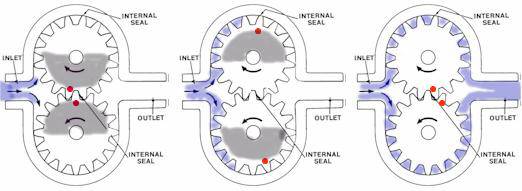
Figure No. 1 shows a simplified drawing of an external teeth gear pump on the left along with the alternate arrangement of internally pointing teeth.
Figure No. 1. External and Internal Teeth Gear Pumps GEAR PUMP DESIGN Gear pumps use toothed gears turning inside a close tolerance housing to draw-in liquid and then squeezing it out ahead of them. Paddle steamers used the same principle of operation. These pumps are positive displacement pumps and anything drawn into them will be forced out. As a consequence they can generate very high discharge pressures. Materials of construction vary from metals of various types and hardness through to plastics of various types and hardness. Maintaining the close tolerances between the housing and the cogs is critical to efficient operation. The clearance between the edges, of the teeth and the housing and the ends of the cogs and the back and front walls of the housing are very small. Between the teeth and housing it is in the order of 0.1 mm (0.004') while the clearances between the front and back faces of the gears and the ends of the housing are only 0.025 mm (0.001'). The fine clearances reduce liquid re-circulation back from the high-pressure discharge to the low-pressure suction side and make these pumps one of the most efficient available. Gear pumps usually have one shaft penetration through the housing for connection to the drive. The gear shafts on the smaller pumps can be supported in journal bearings within the ends of the housing and are lubricated by the product. On larger pumps rolling element bearings mounted in bearing housings are used. To prevent surface to surface contact of teeth the product provides the lubrication.
Continued in "Pump Types Explained" ebook ...
Price: US$
|
Pump Types ExplainedBy Mike SondaliniFree book sample - Contents - Back to Ebook Review The free online ebook sample below is copyright protected. You may not modify, publish, transmit, display, participate in the transfer or sale, create derivative works, or in any way exploit, any of the free online ebook sample content, in whole or in part. GEAR PUMP OPERATION & MAINTENANCE
Figure No. 1 shows a simplified drawing of an external teeth gear pump on the left along with the alternate arrangement of internally pointing teeth.
Figure No. 1. External and Internal Teeth Gear Pumps GEAR PUMP DESIGN Gear pumps use toothed gears turning inside a close tolerance housing to draw-in liquid and then squeezing it out ahead of them. Paddle steamers used the same principle of operation. These pumps are positive displacement pumps and anything drawn into them will be forced out. As a consequence they can generate very high discharge pressures. Materials of construction vary from metals of various types and hardness through to plastics of various types and hardness. Maintaining the close tolerances between the housing and the cogs is critical to efficient operation. The clearance between the edges, of the teeth and the housing and the ends of the cogs and the back and front walls of the housing are very small. Between the teeth and housing it is in the order of 0.1 mm (0.004') while the clearances between the front and back faces of the gears and the ends of the housing are only 0.025 mm (0.001'). The fine clearances reduce liquid re-circulation back from the high-pressure discharge to the low-pressure suction side and make these pumps one of the most efficient available. Gear pumps usually have one shaft penetration through the housing for connection to the drive. The gear shafts on the smaller pumps can be supported in journal bearings within the ends of the housing and are lubricated by the product. On larger pumps rolling element bearings mounted in bearing housings are used. To prevent surface to surface contact of teeth the product provides the lubrication.
Continued in "Pump Types Explained" ebook ...
Price: US$
|
||
|
|
![]()
![]()
![]()
![]()